I used 6oz fiberglass to cover the hull, with medium thickness epoxy. I had to break up the glassing into 2 sections per side, plus the keel and transom, for a total of six work sessions. I wanted to ensure I had enough time to deal with everything – fiberglass angles and folds, keeping a wet edge and finally getting the epoxy slough squeegee’d off. The limiting factor is that once the epoxy kicks and heats up in the container, it gets whitish. If you’re using it then, it will cure a different color than the rest of what has been put on – very visible on the hull. So it was a balancing act.
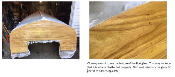
Transom fiberglass, first coat
There are supposed to be 3 coats of epoxy, scuffed with 180-220 grit sandpaper between coats – first coat adheres the fiberglass to the hull, second coat fills the fiberglass weave, and the third coat buries and full encapsulates the wood and fiberglass combination. It ends up being about 3/16″ to 1/4″ total thickness. I used regular paint brushes but trimmed down the bristles so that they would push the epoxy into the weave, instead of smoothly brushing it on. It was messy at first but once I got the right amount of epoxy on the glass, I followed up with a 1/8″ nap roller to spread it more evenly. Then I sqeegee’d off the slough. The vertical surfaces were tricky but it worked out OK.
A great reference on epoxy and fiberglass is a free e-book, Gougen Brothers on Boat Construction. It is written for the West System but has a lot of good info on epoxy chemistry, setup, application and other stuff.
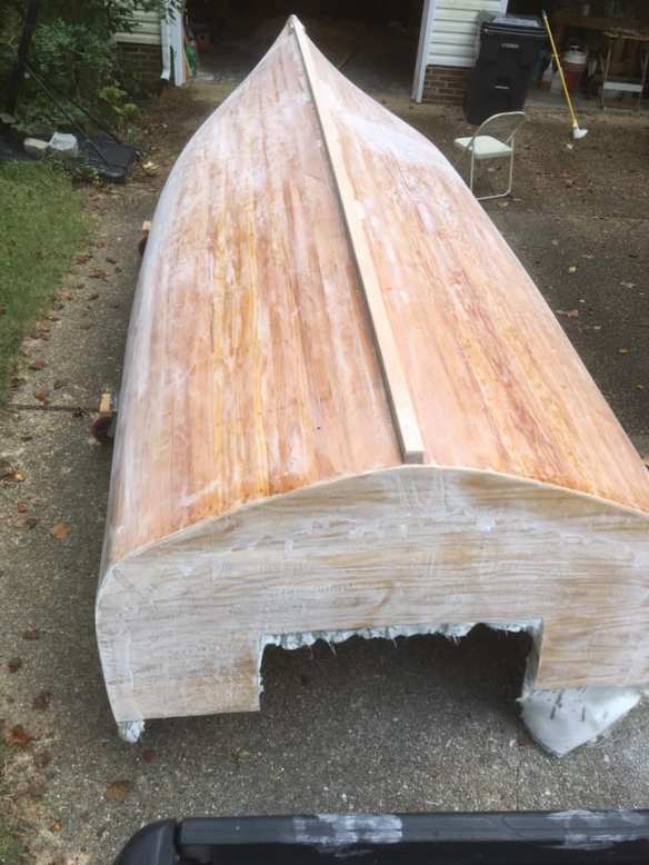
Fiberglass and epoxy, after scuffing up the first coat.
Before I put on any more epoxy, I wanted to get the spray rails attached. I felt better doing this after one coat instead of three of epoxy. Most of what I read recommended to not expose the rails to epoxy so they’ll be easier to remove if needed. Just a personal preference on my part to do it this way.
I scarfed together three pieces of ash to get 20′ lengths for each side. Scarfs are 6″, bottom to top, and taken out with an electric planer. I just stacked the pieces on top of one another and planed them all at once (see below).
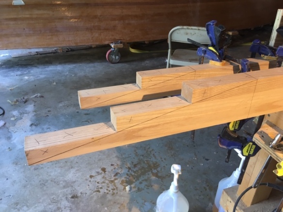
Layout of scarf. X’ed out sections will be removed.
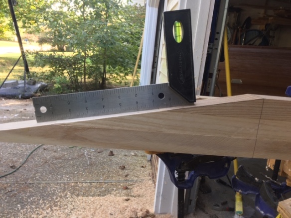
After planing. Flip them over, attach together and epoxy / tighten up
After I attached the scarfed pieces together, I picked off the rail locations on the print and transposed them to the hull. I wanted a more dramatic sweep up near the bow, so I called an audible and deviated from the print. Next I marked off and attached the port rail, dialing it in station by station, drilling pilot holes and countersinks, then making sure I cleared out any drill detritus between the rail and hull. I used 2″ screws and epoxy to attach, along with some makeshift clamping bars that helped me get the rail flush against the hull. The screws went into the ribs, mostly between planks.
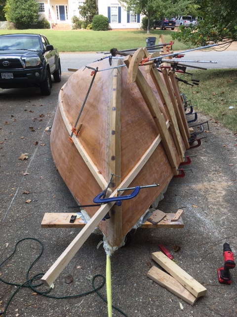
Contemplating the rail to stem connection. Note the clamping setup – very helpful in getting the rail flush against the hull.
The next day I removed the clamps from the port rail and set up on the starboard side. I picked off the port side measurements and transposed them to starboard. There were a little different than plan, so just mirroring the port rail ended up keeping everything symmetrical and passing the eyeball test. I then used the same clamp/screw/epoxy method, with the help of some cargo straps back aft, and attached the starboard rail.
Port rail attached, starboard in progress.
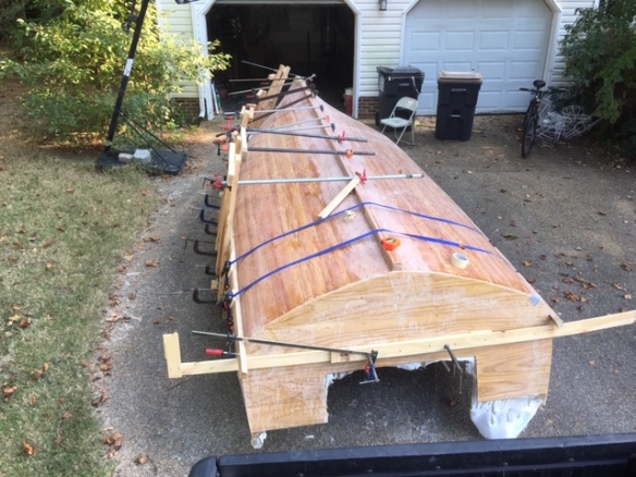
Starboard rail attached
Next step is to finish the remaining two epoxy coats, varnish, and – PREPARE TO FLIP!
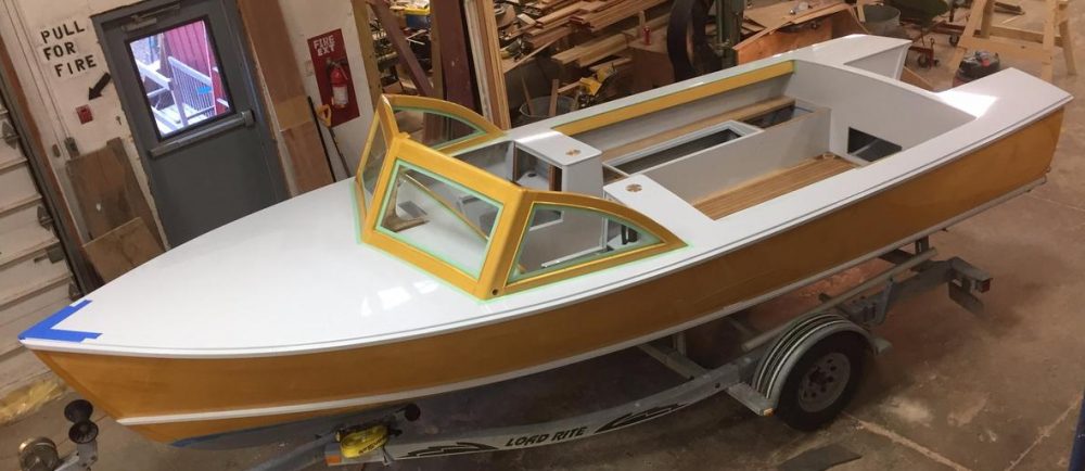
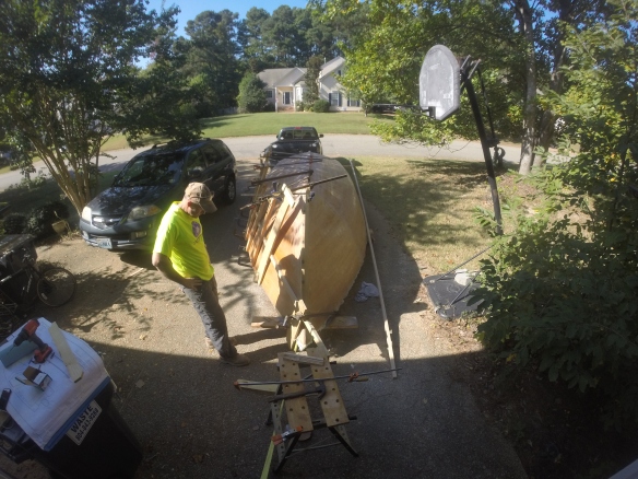
Forward progress!
