My boat build was a success….a full year of use is behind us and I’m happy with the plans, the build process and, of course, this creation that I enjoy so much.The things I was concerned about during the build have amounted to very little now that she swims.The list of things to adjust is short. Over last winter, I moved the driver’s seat back so I could stand while driving, and I added a glovebox for storage.This winter I will add ballast to the bottom center of the boat to smooth things out at anchor, and will increase the size of the limber holes.Neither are major issues but they will make me feel better and let me take care of and be around her a little longer.All that said, this build is not quite over yet…I am in the first stages of writing a book about why I decided to build this boat, the seven year learning-and-doing process and some other things.It’s a very personal story, but it will outlive me and also leave behind something permanent of my Grandparents and my own family.Happy memories should be shared. Forward progress!
Thursday, July 28 was a good day! Sea Trials and my Boating 101 course went well and I brought the boat home. 90 Hp was definitely the right call – the boat got up to 36 mph and took waves and wakes well, didn’t plane too hard or high and overall performed very well.
Getting her into the water – just enough to float off the trailer
My main concern at this point is getting her on and off the trailer. I think I can re-learn how to handle a boat fairly quickly (it’s been a while) but trailering will require some finesse and that’s pretty new to me. I have a single axle with keel rollers and port / starboard roller assemblies for balance. I’ll be doing some research and a few trials.
Tied off and ready to go
The guys at Bill’s Marine Service in Oakland, MD did a great job of getting me up and running. I would imagine they don’t see many homemade wooden boats; everything went smoothly and they kept me very well informed about routing, battery connections and other details that had to be adjusted.
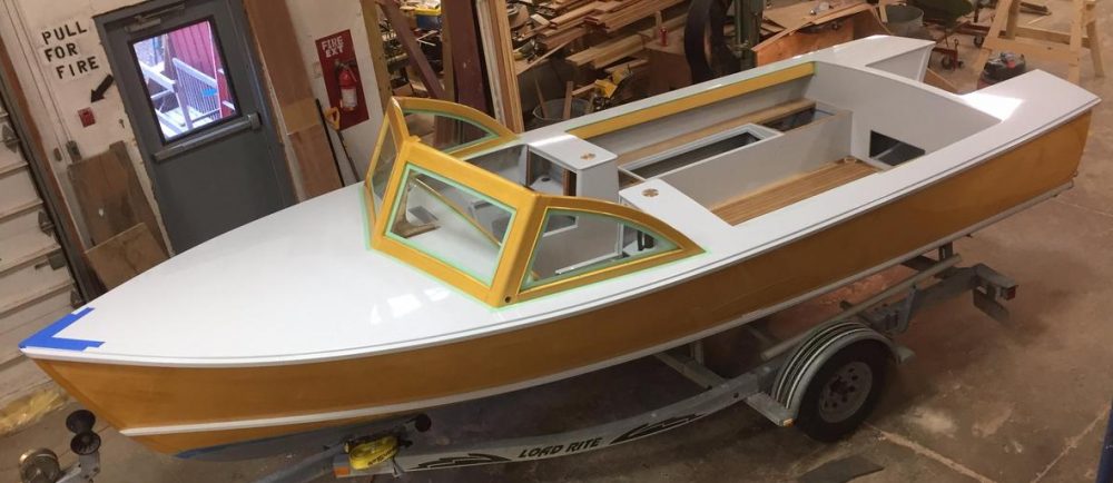
Making wavesThe Amateur Boatbuilder and his creation
I have a few things to address before christening and a shakedown “cruise” but we’re very close to the end of the process – hard to believe. The final step is our tribute to King Neptune and the accompanying launch party. That is scheduled and will be happening soon – pics to come. Forward Progress!
I’m approaching the finish line…as I type this the boat is at the dealer, Bill’s Marine Service in Oakland, MD, getting the engine, steering cable, throttle and controls installed. Life is good!
Dropped off for motor, steering cable, throttle and instrument installation
I towed the boat from my home to the dealer using lots of redundant straps, chains and tie downs. I have a 5k lb ball receiver, straps that can hold 5000lbs, forged eye bolts and tie downs, and of course a spare tire. I put the straps in a forward/aft spring line configuration in addition to those keeping the boat tight against the rollers and keel rests. I did a shake-down the night before and everything seemed to be ready to go, so I left about 3am to avoid heavy traffic and made a few stops to make sure things were good. I was towing with a 2011 Toyota PreRunner and it did well on grades and up/down a couple of mountains to get there. I got about 15mpg vs my normal 21mpg.
Wiring attached to the tops of floor boards.
I rearranged the wiring to run under the floorboards (attached to the undersides, not down in the bilge) and installed inline fuses. The heat shrink connectors and ring terminals worked pretty well once I got the general hang of it. Everything except the bilge pump connects up to the fuse box directly under the dash. I’m using inline fuses in order to keep some of the functionality of the Nilite switches, so the fuse box is basically a bus bar, which is fine. Currently I have four instruments hooked up (horn, port/starboard running lights, transom light and interior lights). The bilge pump is connected directly to the battery vs on the switch panel. I did this as a safety measure – my theory is that it’s better to have a dead battery than a flooded boat.
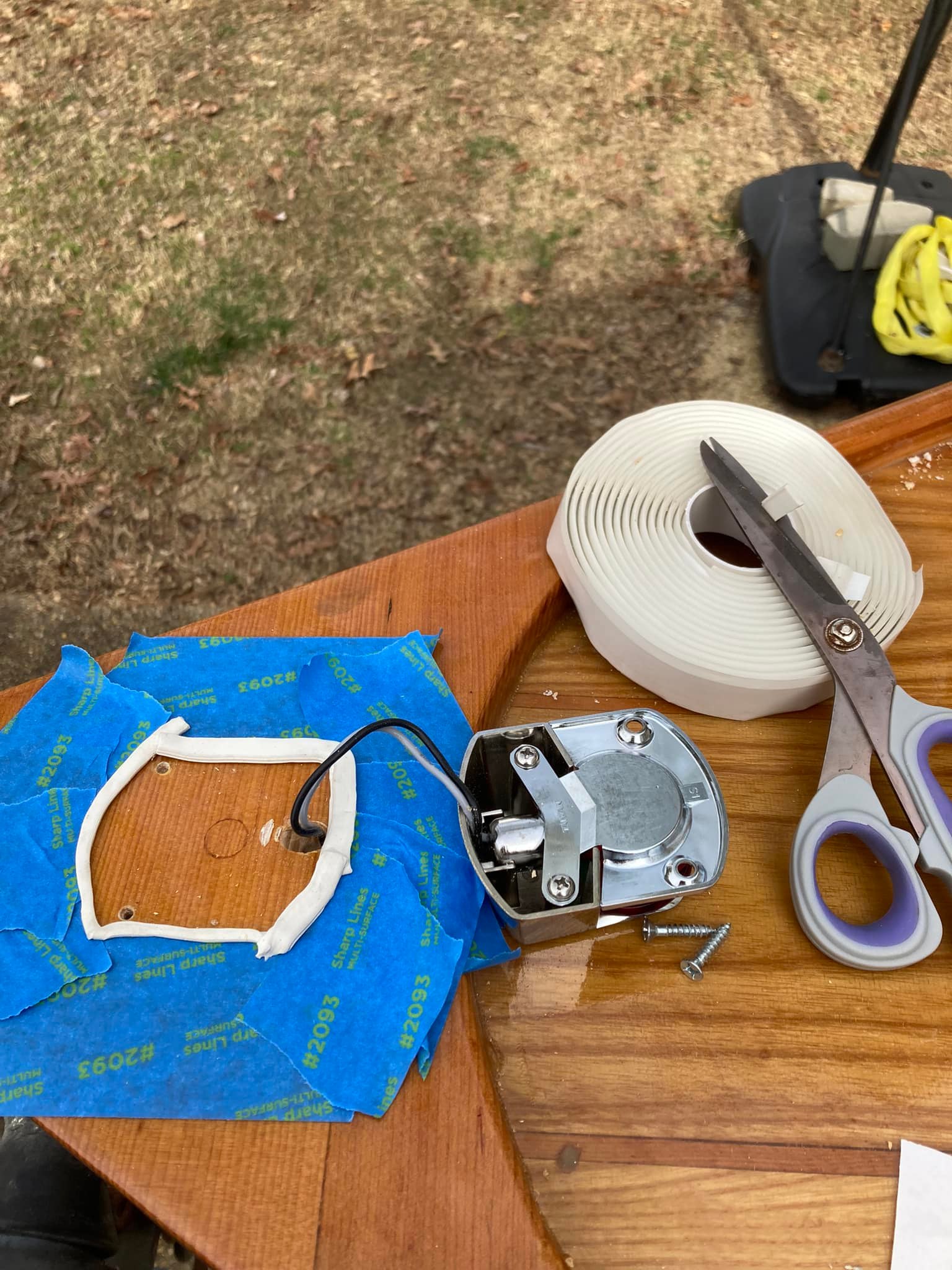
Butyl tape used to ensure a watertight seal for the instruments. This is the port/starboard running light on the bow.
The instruments and folding cleats are bedded down with butyl type, which is a very effective watertight seal. Unfortunately it also gets everywhere and sticks to everything in sight. It got into my folding cleat assemblies and bound them up, so I used mineral spirits to basically dissolve the unwanted material. It worked very well.
Gas tank with strapping block
I installed a 12 gallon gas tank and will likely have a smaller spare tank. I ran the gas line through the starboard foam compartment so it can link up with the motor. I also installed a couple of 4″ air vents so there won’t be any fume accumulation.
7 years of receipts; I used these to estimate a value so I could get a title and registration from the state of Virginia
Finally, I tallied up the receipts I kept over this 7 year odyssey and used them to submit an application for title and registration to the Virginia Department of Water Resources, as well as for insurance purposes. Similar to the application for the trailer VIN and title, I got a very prompt turnaround for the boat title and decals. I’ll apply them once everything is set with the motor.
One thing that surprised me was the lack of boat insurers for wooden boats. USAA, Progressive, and other large orgs no-quoted me, but I was able to get a reasonable quote from Hagerty.
So all that’s left is to pick up the boat after engine installation and testing, apply the tags and pay homage to King Neptune! Forward progress!
Season 8 of buildingaboat….got her out in the sunlight and cleaned / prepped for more work, mostly electrical. Also working on the VIN plate, title and registration for the trailer.
Port sideStarboard sideBow viewAft view
Garage clearance for the wheel wells. So I’ve always heard that a good engineer will make something that works, while a great engineer will make something that JUST works.
So far so good. I can probably remove an inch or two each side from the wheel covers. Need to get the trailer properly registered and insurance before I can get a motor installed too. Will be taking that to a local shop.
I transferred the boat from my homebuilt carriage assembly to the trailer recently. Before I got started I permanently installed a bow eye and two eyebolts onto the transom. Both are used to stabilize the boat onto the trailer when moving or pulling from the water. It was a one man job so I needed mechanical advantage. I could’ve moved it three ways:
by guiding it from my garage down onto the trailer. From the garage, I would’ve controlled the boats descent via a winch connected to the transom eye bolts. I would also have pulled the boat down using the trailer winch. This is the easiest, fastest option.
by jacking up the boat inside the garage, putting it on blocks and removing the wooden carriage assembly as more of the boat was supported by the backed-in trailer.
by lifting the boat via a garage I-beam, stabilizing it with blocks and then removing the wooden carriage assembly as more of the boat was supported by the backed-in trailer. This is the safest option, especially for a one man job.
Boat transfer steps and important mechanical advantages
I chose a combination of options 2 and 3. It was safest to lift the boat with the ibeam, stabilize it in multiple places with concrete blocks, and disassemble the wooden carriage as more of the boat got onto the trailer. That also allowed me to adjust the trailer rollers so they properly met the sides of the hull.
I broke the transfer into three boat sections, bow, beam and transom. I used 12 concrete blocks, 4 at each section and stacked 2 high. I supplemented them with some 2x4s. I did NOT use cinderblocks – there’s a big difference, as they are not strong enough and could’ve easily crumbled.
Boat transferred onto the trailer. Note the yellow strap at the beam. It connects to the hand winch just above the wind shield, which then connects to the ibeam clamp so the boat can be pulled up. It’s a 3k capacity hand winch.
Once the boat was completely on the trailer I salvaged whatever I could from the wooden carriage. I was able to recover a bunch of carriage bolts (or coach bolts as they call them in NZ – shout out to family members down that way!), washers, etc, but not as much wood as I’d hoped. The lengths were just too short or I’d drilled too many holes in them.
1 of my 2 wooden carriage recovery piles.
Once the boat and trailer were in the garage, I got two wheel jacks and placed them under the tires. These jacks go around the wheel and lift it up via a foot pump. Once up, you can pretty much just push the boat around if you’re on a clean, level surface. Currently I have the boat and trailer sideways in my garage until I can get the motor and swing away tongue installed. I may end up having to store it at a marina or indoor storage place – we’ll see. Plus I need to make room for the next project so I need an empty garage.
Wheel jack #1 of 2. Pump the black foot pedal until the tire clears the floor then lock in place. Then the boat can be easily moved.
I also have all the gear needed for the electrical system now. I made a trip to West Marine for the big stuff but got the instruments, wiring, etc from various other places. Learning how to do that should be fun – electrical has always been a mystery to me but I have a family member coming (who’s a master electrician) so that should help. After that the major steps are a license for the trailer and getting the motor.
I can finally see the finish line. Forward progress!
Second coat of epoxy plus 2 coats of varnish. During epoxy application I went over it with a heat gun to pop the small air bubbles. Otherwise they dry in permanently.
I added a second coat of epoxy and a couple coats of varnish to the deck. This provides structural rigidity, makes it waterproof, sun-proof, and of course makes it look good. Varnish application should be via the roll and tip method – using a 1/8 nap roller, apply thin layers / small amounts of varnish in short strokes and then tip off with a fine brush. Keep spreading the varnish, otherwise it may pool up, which causes it to wrinkle and get gummy and yellow. I dealt with this in certain sections over the past month – only way to fix it is scrape it off and re-apply the right way.
Template for the port foam compartment. Make sure to leave enough room to pour in the foam at top.
Next I made the foam compartments. Plans call for 4 cubic feet of 2 lb foam, which should offset about 350lbs of weight at the transom. This will counteract the weight of the outboard, gas tank and batteries, so it’s definitely a requirement. To make the compartments, I used one of my best tools, a hot glue gun, to get the right shape and make a template. I then cut the shapes out of 3/8″ marine plywood, made the tops, and dry fit everything together to make sure it’ll work, which it did. I then hid some 2×4 guides for everything to screw into, so it’s nice and rigid. The foam is 2 part, mixed together. You have to mix it in high-ish heat, more than 80 degrees F, really fast for about 20 seconds and then immediately pour. It expands to 25x the volume. It can be dangerous – a heavy by-product is CO2, so that means a heavy fan, plenty of ventilation and probably a spotter. I’ve also read about people buying foam boards at the hardware store and just stacking them into the compartments. The engineer in me doesn’t like that so I just went with what I thought the designer wanted.
Starboard foam compartment, dry fitted, pre-epoxy. The top is removable and there’s enough room to pour in the foam.
I also bought a trailer recently. It was my second attempt – the first was 2-3 feet too short and I just couldn’t live with that – the center of gravity would’ve been off, other drivers probably wouldn’t have seen my brake lights, etc, etc. So I sold it – only 8 hours on Facebook marketplace and it was gone. Pictured above is my second attempt. It has everything I wanted except a swing away tongue, which I can install. The critical factors for a trailer are weight and length – what the trailer can carry and whether or not it supports the boat properly. There are lots of ways to find this out – the best way for the weight is the trailer VIN plate and for the length of course just use a tape measure. The winch can usually move forward or backwards so that should be taken into account as well. You also need to know your trucks carrying capacity, or Gross Vehicle Weight Rating. I recently installed a towing bar with a two inch hitch, which put me at about 5000lbs. The Albury plans say the boat is 2400lbs dry weight (without fuel, water, motor, etc) so I should be good to go. Now I just have to move the boat from my home-built carriage to this trailer. That’s another episode!
Floor boards out and sanded, ready for varnish
I also put a final coat of varnish on my floor boards. Not too difficult but in order to prevent wrinkling and gumminess I had to really get a good rough surface. I used ceramic sandpaper pads and will never use any other kind again. They didn’t load up and they lasted twice as long.
The windshield hasn’t been too bad. I’m at the point where everything is a one-off but that’s OK…because I kind of like building this boat.
Here’s the objective – as you can see geometry is important here (thank you Mr. Hull!)
Windshield plan
The first step was building the windshield knee. I glued up some leftover face-grain planking, planed it to 1 3/4″ thickness and then cut a shape that looked like the plans. I then rounded over the edges. The most important part was getting the angle right, about 30 degrees, and then matching the bottom so that it was flush against the deck.
Windshield knee, post shaping
After attaching the knee, I cut and attached the centerpost and bottom runners. I cut a 15 degree angle fore to aft on the centerpost outer face, as well as routing a 1/4″ groove about 1/2″ deep. This centerpost groove, as well as an accompanying one in the runners, will receive the acrylic windshield. The angles were also 15 degrees fore to aft. The most important step here was to make sure I was properly aligned with the boat’s centerline on both the windshield knee and the knee-to-centerpost attachment point
Centerpost attached to windshield knee, with bottom runners dry fit. The smaller knee is for the side posts.
Next step was to attach the side posts and align with the bottom runners. I wanted them to be the same distance and same angle from the centerpost. They also got 1/4″ routing grooves that were 1/2″ deep, for the side windshields as well as for the main windshield. I had a scrap piece of acrylic that I laid in the grooves to make sure everything lined up.
Center and side posts attached, with bottom runners.
I then finished the tops and slid in the acrylic. I thought an angled look would be better for the side windshields but quickly changed my mind upon seeing it from a distance.
Windshield dry fit, first attempt
I then decided to steam two top runners for the side windshields. I routed a groove and then steam bent them to the same shape. After they dried, I attached them, which involved some angled cut adjustments to the bottom runners along the gunwales.
Windshield dry fit, final attempt. I like the side windshields much better this way than angled.
My biggest lesson on this part of the build was my choice of sealant. I used a flexible, clear silicon for the acrylic to nest in, which would’ve been OK if it wasn’t so tacky and didn’t smear everywhere. But I was able to get most of the smearing off with mineral spirits and a toothbrush. It took a while though.
Next step is to epoxy the windshield; the epoxy coat will lock in the shape and fill any voids. Forward progress!
It’s been a while since the last update…I’m pushing to have her in the water by summer 2021. So here goes…
I traced out both quarterknee borders and then glued up 3 sections of 3/4″ marine ply. I then cut them and dry fit them for installation in the motor well – these will eventually be covered by a 1/4″ decorative overlay but are important for hull stability and protecting the aft section from motor vibrations. I attached them with 5200 and screws. I used 5200 for its flexing properties.
Quarterknees, glued and screwed.
Next up was the foredeck. This is the area in front of the windshield that I plan to lounge around on when at anchor in shallow water near home. I used a base of 1/2″ plywood and then put on alternating strips of 5 1/2″ ash and 1/4″ douglas fir; the rest of the boat is ash and dfir, so this matches up. I attached the plywood to angled deck beams with screws and 5200, cut off the overhang and then fiberglassed over the ash/dfir strips.
Foredeck 1/2″ plywood base. Deck beams are under the ply; ply is marked so I’ll know where to drill for the screws.Alternating ash and dfir strips on the foredeck. They are attached to the plywood with epoxy and clamped down with excess wood pieces in this pic.Foredeck, after all of the overhang was cut away. Rub rail will cover up the seam.Foredeck post fiberglass
Next step was to install a rub rail. This was harder than I thought, mostly due to the type of wood (ash) and its dimensions. It took a lot to get the 2 1/4″ wide, 3/4″ ash up flush against the sheer. It would’ve been better to use a wood cut with less mass, or maybe to steam the ash and then install. Either would’ve made these pieces easier to pull in and secure.
Ash rub rail with dfir plugs. I attached the rail with thickened epoxy and screws. I put coarse salt in the epoxy to keep the rails from slipping.Attached section 1 of the starboard rub rail. Lots of clamps and screws to pull it in to the sheer.
Like the foredeck, I used 1/4″ ash on top of the sheer clamps. The angle of this wood overlay changes as you move down the length of the boat, so there was anywhere from 1/2″ to 2″ of overhang to cut off at various places, but the important thing was that I was able to match up the grain.
Sheer clamp rough cut an attachment. Able to match up the grain patterns pretty well.Sanded sheer clamps, both sides. Routing a smooth, clean surface on the sheer clamp. I screwed in a batten in order to keep a straight cut.
Finally, I made a couple of mascots of the boat. It was a fun little project and I was able to give one to my father as a Christmas present, which he got a kick out of. I got the idea from this website. Basically just a block of leftover dfir that I glued a template onto, cut to shape with a bandsaw, and then sanded until my fingers bled…but it was fun.
Mascot #1 and his big brother.
I’m currently in the middle of the windshield build. More to come on that. Forward progress!
I’ve been doing a lot of boat work over the past month, and luckily things are moving along pretty quickly. The learning curve has kicked in and I’ve been able to get most of these smaller projects done and accurately fitted up. I’ve put in the sheer clamps, deck beams and breasthook. I’ve fitted up the forward platform and aft bulkhead.
The sheer clamps provide surface area for attaching the gunwales and run from stations 1-10 (between the 2x4s running athwartships on the boat carriage. I countersunk 3 1/2″ screws to maximize the holding force, plus epoxy. Finally I matched the bevels with the deck camber, but I expect that will need fine tuning later on.
3 1/2″ stainless screws
Cutting off the excess at station 1
Finished sheer clamps (between the 2×4’s running athwart the boat carriage)
Next up were the deck beams and breasthook. I cut them with a 1” camber from centerline to gunwales, sloping to flat at the bow. I found the angles by hot gluing a shim on each side and transferring it to the beam for cutting. I then connected the lines with a bevel gauge and cut along the pencil lines for the required angles. I’ve also epoxied / sealed them.
The breasthook is six 2x3s that were glued together, planed smooth on both sides, cut to fit, and then screwed in through the planks. I left notches on the sides for clamping. Since installation I have epoxied it.
Deck beams cut and in place
Hot gluing to find the angles required for the beam to fit. The stacked up shims under the board lift it up to the appropriate camber height I want at the centerline.
Breasthook in place. Note the notches, needed to pull it up tight against the stem.
I laid out and found the shape of the forward platform with shims and a hot glue gun. I transferred the rough shape to marine plywood and then made my finish cuts with a router. I put a 45 degree bevel along the entire length so that it snugs up against the hull. I’m a little concerned about whether or not I’ll need to get under it at some point; I need to address that before final enclosure. Either way I’ll only screw it in, i.e., no epoxying it to the platform beams.
I followed a similar process for the aft bulkhead. This panel is basically a “wall” between the motor well and rear seating. I’m using AB marine plywood with the B side facing the transom so nobody sees the patches. This enclosure between station 1 and the transom is where the gas tank and any ballast is located. It’s also where the motor is mounted.
emplate for the aft bulkhead
Aft bulkhead rough fit.
One lesson learned that I want to pass on is the marine plywood transportation. I was on the fence about whether my short bed truck could handle it and was going to either rent a long bed truck or have it delivered. Instead I decided to mount 2×4’s in the truck bed notches and insert another brace in the space between my tailgate and bed. I then used a 30′ strap with hooks and shackles to brace the panels up to connection points in my truck bed.
The truck bed has 2 notches on each side for 2×6’s or 2×4’s.
Panels in the truck bed with a strap hooked and shackled at various points
Current work is epoxying / sealing the platform and aft bulkhead; I’m doing this outside of the boat to prevent inadvertent attachment to platform beams. Next up is shaping and installing quarter-knees in the motor well, and rough cutting the deck panels. FYI: My daughter says hi to dad’s followers 🙂
I recently sealed the stem to plank surface. I used 5200, which is a flexible sealant aptly nicknamed “devils glue”. I’ll need the flexibility since most of the winching and pulling forces will be applied at stem. I even made the epoxy fillets with a pencil eraser end, although that pencil is now ruined. The epoxy fillets will prevent water intrusion and add strength against flexing forces while in the water.
Our cat came out to inspect the work…the looks and judgement were reminders that I needed to keep busy or be in trouble. Kind of like a Master-at-Arms or Chief Boatswain Mate!
I also got the motor well epoxied. This space will be where the motor and fuel tank live. It will be enclosed with marine plywood on top and immediately in front. Epoxying vertical surfaces is tricky; I had to keep working the epoxy until it got slightly foamy, then even it out with a wide putty knife until the epoxy started grabbing the knife. Really like how that transom knee looks though.